


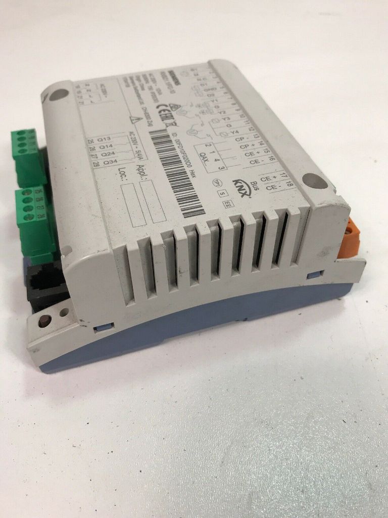


Item details
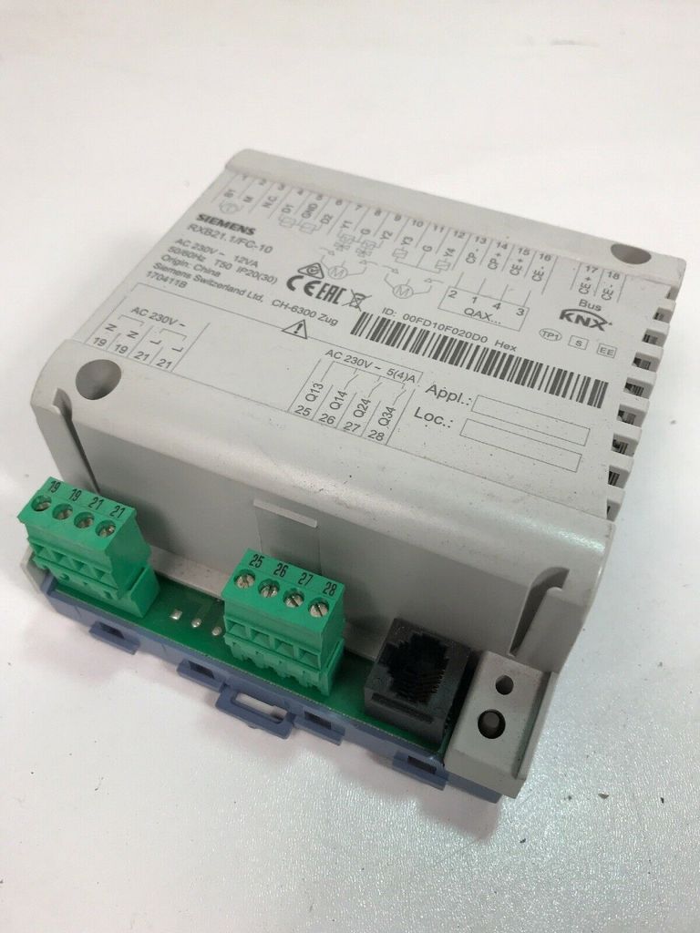
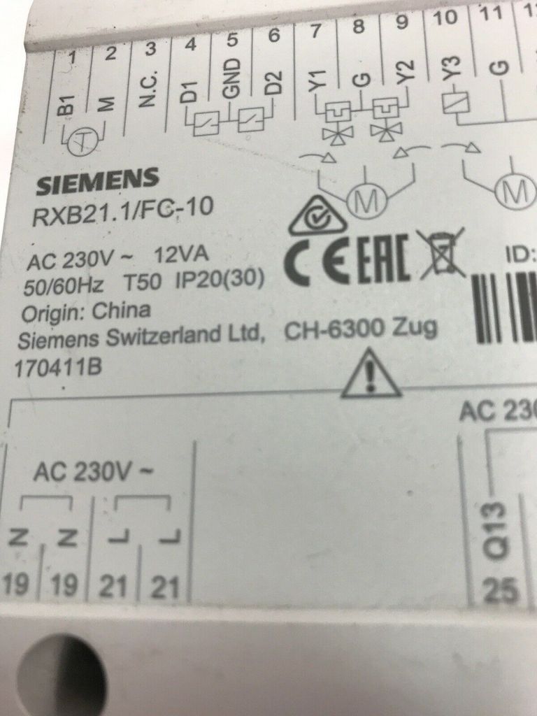
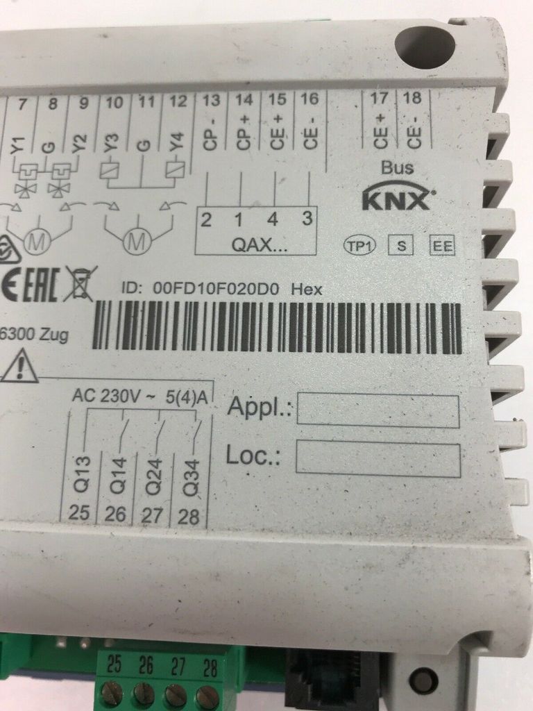
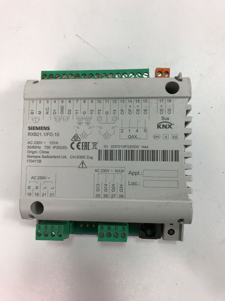
Siemens
RXB21.1/FC-10
KNX
Bus
Room Controller
Room controllers RXB21.1 and RXB22.1 for fan coil applications FC-10, FC-11, FC12 with Konnex bus communication (S-mode and LTE-mode) The room controllers RXB21.1 and RXB22.1 are used for temperature control in individual rooms.
• For 2- or 4-pipe fan coil systems, with or without changeover
• PI control • Konnex bus communication (S-mode and LTE-mode)
• Integration into the DESIGO building automation system via PX KNX
• Integration into Synco
• Control of thermal valve actuators (AC 24 V PDM 1)), of motorized valve and damper actuators (AC 24 V, 3-point) or of electric air heaters
• Use of motorized KNX / EIB bus valves
• Potential-free relay contacts for fan control and electric air heaters
• Commissioning via ETS Professional, Synco ACS or "HandyTool"
• Operating voltage AC 230 V • Plug-in screw terminals 1) PDM = Pulse-duration modulation 2/16 Siemens RXB21.1, RXB22.1 – Room controllers CM2N3873en_11 Building Technologies 2016-05-18 Application The room controllers RXB21.1 and RXB22.1 are optimized for the control of fan coil systems in individual rooms. The following variants can be implemented for fan coil systems
• RXB21.1: 1- to 3-stage automatic fan control
• RXB22.1: 1- to 3-stage automatic fan control with integrated relay for electric reheating The application, hereinafter referred to as "application", is determined by the application software. The controllers are supplied with a fixed stored application group consisting of various individual applications. The definitive application is selected and activated during commissioning with one of the following tools:
• ETS Professional (EIB / KNX Tool Software)
• Synco ACS
• Addressing mode (ACS / ETS)
• Error (if not in addressing mode) Orange / green flashing Parameter download OFF
• No supply voltage
• Error
• Service LED software-wise switched off Other patterns
• Startup (approx. 5 sec) • Error The programming button is used to identify the controller during commissioning. Once the programming button has been pressed, the red programming LED lights up until the identification is complete. After pressing the programming button, the tool overwrites the physical address in the room controller. If the terminal cover is not mounted, the programming button may only be operated by an electrically instructed person! Adjacent terminal can carry mains voltage. Service LED Programming button 5/16 Siemens RXB21.1, RXB22.1 - Room Controller CM2N3873en_11 Building Technologies 2016-05-18 Terminal covers (RXZ20.1) are optionally available, which protect the connection terminals from contact and contamination. The programming LED is visible even with the terminal cover mounted; the programming button can be operated with a tool. The cable routing to the room controller is done by breaking out the cable entry grommets. 3873J02 Removing the terminal cover Identification number (Unique Serial Number) Barcode of the ID, Code 128 Degree of protection Temperature range (0 ... 50 °C) Serial number Test date, series (Z, A, B, C ...) Observe the notes in this documentation Activated application Location 3873Z04 010025CA9900 060215B 513 Use of the labeling fields "Appl." and "Loc.": Handwritten entry of the location and the activated application group. All terminals are pluggable. To avoid wiring errors as much as possible, the terminals to which AC 230 V can be connected (relay outputs) are spatially separated from the other terminals. Warning! A strain relief for the cables to terminals 19 ... 28 (AC 230 V) is absolutely necessary. The cables must be fixed to the provided lugs on the housing base with cable ties (see picture on the right). Plug-in terminals to which mains voltage is connected must be de-energized before plugging in or unplugging! 3873J04 Terminal cover Imprint (example RXB21.1) Note Connection terminals 6/16 Siemens RXB21.1, RXB22.1 - Room Controller CM2N3873en_11 Building Technologies 2016-05-18 The RXB2... room controllers communicate with other devices via the following interfaces:
• PPS2 interface (proprietary) for data exchange with the room devices
• KNX / EIB bus (terminals CE+, CE-), for communication with: Interface PX KNX (to DESIGO INSIGHT) Interface OCI700 / OCI702 (to Synco) additional RXB controllers KNX / EIB-compliant field devices (e.g. temperature sensors) The connection of the tool plug (RJ45) may only be carried out by an electrically instructed person! The adjacent terminal can carry mains voltage. The tools ETS Professional or Synco ACS can be connected to the system at three different points (A) to facilitate commissioning: − on the KNX / EIB bus cable at any point − on the RXB2... controller (tool connection socket RJ45) − on the room device (tool connection socket RJ45). A A A A A B B • The tool connection socket is proprietary. A Siemens connection cable must be used (e.g. PXA-C1). When connecting to Ethernet, the device at the other end can be destroyed!
• The ETS and ACS tools require an interface, even if they are connected to a tool connection: RS232-KNX / EIB interface (ETS) USB-KNX / EIB interface OCI700 / OCI702 (ETS , ACS).
• The "HandyTool" is connected to the tool connection of the controller or to the tool connection of the room device (QAX3..., RXZ90.1) (B).
• If you use an OCI700 / OCI702 as an interface, it is connected to the service socket of the controller or the room device. As long as the OCI700 / OCI702 is connected to the service socket, it must be powered via USB from the computer. Otherwise, the LCD display of the room device will go dark, and the controller will go into the addressing mode. Tool connection communication notes Caution! 7/16 Siemens RXB21.1, RXB22.1 – Room controllers CM2N3873en_11 Building Technologies 2016-05-18 Disposal The device is considered electronic waste within the meaning of the European Directive 2012/19/EU and must not be disposed of as household waste. • Dispose of the device through the designated channels.
• Please observe the local and currently valid legislation. Project planning instructions The KNX / EIB project planning manual Building systems technology and system basics (see literature reference page 11) contains the relevant information for KNX / EIB bus project planning (topology, repeaters, etc.) as well as for the selection and dimensioning of the connection cables for power supply and field devices. • The room controllers RXB2... are operated with mains voltage AC 230 V. Actuators (valves, damper drives) are directly powered by the room controller. Therefore, no separate AC 24 V power supply is required for the controllers and their field devices.
• The dimensioning and fusing of the supply lines depends on the total load and local regulations.
• A looped power supply is interrupted when the 19/21 plug is disconnected from the controller. (the 19-19 and 21-21 bridges are on the board, not on the plug, see terminal diagrams on pages 11 and 12) • The power supply lines must be secured with a strain relief at the room controller. The potential-free relay outputs allow switching of loads up to AC 250 V, 5 A (4 A). The air heater relay in the RXB22.1 switches loads up to 1.8 kW resistive. The dimensioning of the lines depends on the connected load and the local regulations. The circuits must be externally fused (≤ 10 A), there is no internal protection. The lines must be secured with a strain relief at the room controller. Fans must not be connected in parallel. The simultaneous load of the outputs Y1 ... Y4 must not exceed 9.5 VA. Y1 (Heating) 2 thermal valve actuators STP73 5 W Y2 (Cooling) 2 thermal valve actuators STP73 5 W Y3, Y4 (Outside air) 3-point damper actuator 4.5 VA 4.5 VA The maximum load is 9.5 VA each in the heating and cooling sequence. This is permissible because the two sequences are never active simultaneously. For small loads (< 2VA) the voltage tolerance may be > +20% (see technical data). Power supply lines AC 230 V Potential-free relay outputs AC 230 V Triac outputs AC 24 V Example: 8/16 Siemens RXB21.1, RXB22.1 – Room Controller CM2N3873en_11 Building Technologies 2016-05-18 Mounting instructions The room controllers can be mounted in any position with the following mounting options: 3873J06 3873J07 DIN rail mounting The base of the housing is equipped with a snap-in device for mounting on DIN rails, type EN50022-35x7.5 (can be unclipped with a screwdriver) Direct mounting For mounting with screws, there are two drill holes (see "Dimensional drawings" for the drill plan). The base of the housing has raised bearing surfaces. Screws: ∅ max. 3.5 mm, length min. 38 mm STOP Note! Tightening torque of the mounting screws max. 1.5 Nm When mounting, the following points must be observed: • The device must not be freely accessible after installation. It must be mounted in a control cabinet or behind a cover that can only be opened with a key or a tool • The heat generated during operation must be dissipated; sufficient air circulation must be ensured
• Good accessibility for service • Observe local installation regulations The installation instructions incl. drilling template are printed on the device packaging. Commissioning instructions The commissioning of the RXB2... room controllers is done with one of the tools ETS Professional or Synco ACS - via the RS232-KNX / EIB interface - or the USB-KNX / EIB interface (OCI700 / OCI702), or with the "HandyTool" via PPS2 The "Appl." and "Loc." labeling fields are filled in with the current application and location during commissioning. In a special test mode, the outputs can be controlled (ETS Professional or "HandyTool"). If the digital inputs are activated, they can be queried. Labeling Functional test 9/16 Siemens RXB21.1, RXB22.1 – Room Controller CM2N3873en_11 Building Technologies 2016-05-18 STOP Caution!
• In case of a prolonged short circuit (approx. 4 minutes) or overload, the thermal fuse in the transformer may trip. The device must then be replaced.
• On the AC 24 V side, there is no protection against miswiring with AC 230 V.
• The AC 230 V mains voltage for power supply and relays must be switched off before plugging in and removing the pluggable terminals (danger of electric shock!)• A looped power supply is interrupted when the 19/21 plug is disconnected from the controller. (the 19-19 and 21-21 bridges are on the board, not on the plug, see terminal diagrams on pages 11 and 12). Technical data Power supply Operating voltage AC 230 V ± 10 % Frequency 50/60 Hz Power consumption incl. connected field devices max. 12 VA Internal fuse Thermal, irreversible External fuse for supply line Slow-blow fuse max. 10 A or circuit breaker max. 13 A Tripping characteristic B, C, D according to EN 60898 Control data Control algorithm PI Input signals Alarm inputs D1, D2 Number 2 (for potential-free contacts) Contact voltage DC 16 V Contact current DC 5 mA Contact resistance max. 100 Ω Contact insulation resistance min. 50 kΩ Switchtime: min. 20ms "ON", min. 20ms "OFF" Measuring value input B1 Connectable temperature sensors LG-Ni 1000 Number 1 Measuring range 0 ... 50 °C Sensor current 0.5 mA Resolution 0.1 K Measurement error at 25 °C sensor temp. (without cable) max. 0.5 K Outputs Triac outputs AC 24 V, Y1 ... Y4 Number 2 (RXB22.1) 4 (RXB21.1) Output voltage AC 24 V ON/OFF, PWM or 3-point +/- 20% (with load <2VA: possibly >+20%!) Permissible load current max. 0.5 A Current limitation No internal limitation Total rated load (with simultaneous loading of the outputs) max. 9.5 VA (e.g. 2 therm. valves STP73 per heating and cooling sequence + 1 damper actuator 4.5 VA) Relay outputs Q14, Q24, Q34 Number 3 Relay type monostable Contact rating at AC voltage Switching voltage max. AC 250 V, min. AC 19 V Rated current resistive / inductive max. AC 5 A / 4 A (cosϕ = 0.6) Inrush current (200 ms half-wave time) max. 20 A Switching current at AC 19 V min. AC 10 mA Contact rating at DC voltage Switching voltage max. DC 250 V, min. DC 5 V Switching current at DC 5 V min. DC 100 mA Switching capacity max. 20 W Inductive load L/R max. 7 ms Q44 Relay type monostable Contact rating at AC voltage Max. permissible load (purely resistive) max. 1.8 kW Fuse External fuse for supply line(s) Slow-blow fuse max. 10 A or circuit breaker max. 13 A Tripping characteristic B, C, D according to EN 60898
Find more new and used items in our shop!
International shipping costs on request!
Legal information - click for details